Advanced Realtime Glass Refraction Simulation With WebGL Using a Pre-Calculated Refraction Map

View the original article at http://developers.sky.com/ or download the whitepaper
About
One of Sky’s key brand identities is its glass logo. When Digital Engagement took on the Prospect Homepage we had the opportunity to rebuild the 3D logo that greeted prospective customers.
The original logo never looked quite right, used a high resolution 3D mesh, and a large JavaScript 3D graphics library called THREE.js. It used a lot of hardware resources and was barely used because it looked so ‘off-brand’.

This article describes the process and development of a new rendering technique we created to render the Sky logo using pure GLSL, making it compatible with WebGL and OpenGL capable devices.
Introduction
Refraction simulation using hardware shaders is a widely used technique in real-time computer graphics to emulate translucent materials like glass and water. Most techniques are dependent upon the normals of mesh faces, meaning realistic effects require a high resolution mesh; therefore realism has a steeply inverse relationship with performance.
For web graphics especially, performance issues are even more important because of the wide range of devices on which the application can be executed. Traditional refraction shader techniques work well in dedicated applications like games, however they can be too intensive for in-browser graphical experiences.
The technique outlined in this paper describes how to create a very realistic real-time refraction simulation with very little overhead to the GPU.
In Chapter 2 we will discuss how two commonly used methods work, and how they provide a good approximation of refraction, along with their limitations.
Chapter 3 introduces 2D Per-Pixel Refraction Simulation and the generation of a Refraction Map from a high-end 3D modelling application.
Chapter 4 demonstrates how to drastically improve the quality of the technique using a pseudo high colour-depth UV Gradient Map to generate the Refraction Map.
Chapter 2: Normal Mapped Refraction
A Normal mapped refraction uses the normal data stored within a normal map to calculate the refraction texture map in real-time. This allows us to calculate a good approximation of how the surface of an object will refract the light passing through it.

Figure 1: A traditional normal map has colour channels that represent three dimensional axes. In 2D, only the red and green channels are required.
2.1: Using Snell’s Law
A true scientifically accurate refraction simulation shader is beyond the scope of this paper, but can be summed up as the following:
Snell’s Law describes the way light passes through objects and how it’s refracted by the material’s physical properties. [1]
Using each texel in the normal map we can compute the refraction angle using Snell’s Law in order to calculate a refraction map. (see figure 2)

Figure 2: Snell’s Law creates a close approximation of realistic refraction.
An incidence ray, P, is projected from the camera, to the position of the pixel being processed. The incidence ray is then multiplied with the inverted normal by a refraction index in order to resolve the refraction ray Q.
Because the effect in the context of this paper is 2-dimensional, the lengths of the incidence ray P and refraction ray Q would be hypothesised, and represent the z-depth of the camera, object, and the background. The points of intersection are then transformed to create a UV lookup of the refraction texture.
This calculation is quite complex, and unnecessary for most real-time non-scientifically accurate applications, so a far simpler technique is often more appropriate.
2.2 Using a Basic Approximation
A very basic approximation of the effect can be achieved by using a normal map to simply offset the UV lookup of the refraction texture. [2]
The value of each normal map colour channel should be normalised to floating point numbers between 0.0 and 1.0, then transformed to -0.1 to +0.1. The result is then multiplied by an arbitrary refraction factor to increase the aesthetics of the effect.

Figure 3: A basic approximation of refraction using a normal map to offset the refraction texture lookup. In this example a diffuse texture is blended with the result to add shine.
This technique was adequate for Sky’s 2015/16 branding as the refraction in the logo followed the contour of the surface of the mesh. When Sky rebranded in late 2016, the refraction used in the glass-mark was far more complicated, and so a more advanced technique was required.
Chapter 3: Pre-calculated Refraction Mapping
A normal map only provides data about the surface of an object. Calculation is still required on every frame update to create a refraction map, and the artist has little control over its effect.
Sometimes a material has sub-surface imperfections, impurities, and other natural factors that might affect the index of refraction. These would be far too expensive to calculate in real-time, so requires pre-calculation.
We developed a technique that allows you to take pre-calculated refraction data generated by a 3D modelling application, such as Cinema4D or Maya, and use it in real-time to affect a texture map.
The first step in creating the refraction reference map, is to create a UV map where each pixel has unique shades of red and green. (see figure 4)

Figure 4: A UV gradient map where the red channel represents the X axis, and green represents the Y axis.
The UV gradient map is then taken into a 3D modelling package, and used as a refraction texture or environment map in an object’s material. The result is rendered in high quality, and exported as a refraction reference map. The artist has full control over the refraction using controls provided by the package.
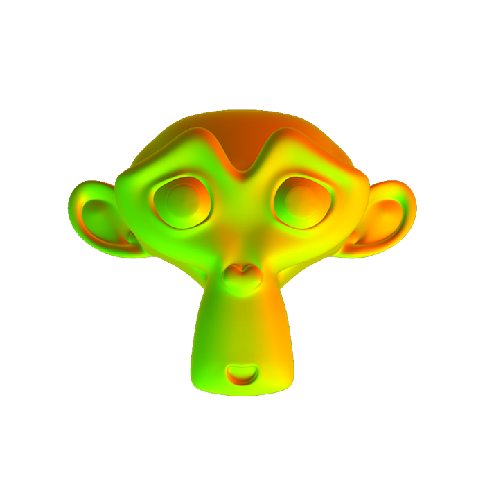
Figure 5: A refraction reference map rendered from a high-end 3D modelling application
The refraction reference map’s red and green channels exactly represent UV coordinates in the Refraction Texture Map, and doesn’t require any further calculation by the GPU.

Figure 6: Final result
Because distortion information about every pixel in the refraction texture is stored within two colour channels of the refraction map, it’s important to have enough colour depth information in the file.
This technique is adequate for applications that support high colour-depth file formats, but a slightly different technique is required for anything with 8-bit colour channels and below.
Chapter 4: Creating a Pseudo High Colour-Depth Refraction Map
Currently, the industry standard, including web graphics, are 24-bit images. This means there are only a maximum of 256 intensities per colour channel (8-bits) with which to store the refraction data.
This can cause pixel stretching, resulting in excessive banding in any rendered output larger than 256 x 256 pixels.
In order to create a high quality refraction effect at higher resolutions, it’s vital to store extra colour depth information using the available colour channels.

Figure 7: Texture maps can result in banding if they don’t have enough colour depth.
A way to get around this issue is to use the 3rd colour channel (blue) as an offset. The 256 x 256 pixel UV gradient map should be tiled 256 times with the blue channel used to offset each instance.
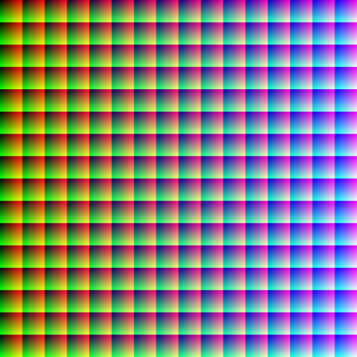
Figure 8: A pseudo high colour-depth UV map
When this map is used within a 3D modelling package, a refraction map is generated with 256 times more fidelity. Like a normal map, the map contains pure reference data, so the map should be created, and rendered without any anti aliasing, or filtering, as they will introduce artifacts such as ‘cracking’.

Figure 9: A pseudo high colour-depth refraction texture map.
When the refraction simulation is combined with a diffuse layer you can create very realistic glass simulation in 2D.

Figure 10: The final result, blended with a pre-rendered diffuse layer to provide the shine.
Conclusion
For non-scientifically accurate applications, it is much more efficient to pre-calculate a refraction reference map offline using a dedicated 3D ray tracing package. Not only does it remove the requirement for any real-time GPU calculation, or making do with rough approximation from normal data, it also gives the artist more control over incredibly complex effects.
Replacing THREE.js with pure WebGL removed ~500Kb of code, and using refraction maps instead of a 3D mesh saved an extra ~750Kb. The Page load time (including script execution) went from 1170ms to 50.46ms, with a massively reduced resource load, mobile phone support, and reduction in battery power usage.
GLSL Code
precision mediump float;
  uniform float scrollOffset;
  uniform float refractionAmount;

  // our textures
  uniform sampler2D u_normal;
  uniform sampler2D u_diffuse;
  uniform sampler2D u_reflection;

  varying vec2 v_texCoord;

  void main() {
    vec4 diffuse = texture2D(u_diffuse, v_texCoord);
    vec4 normal = texture2D(u_normal, v_texCoord);

    float u = normal.r * 16.0;
    float v = normal.g * 16.0;
    u += floor(normal.b * 16.0) * 16.0;
    v += mod(normal.b * 255.0, 16.0) * 16.0;
    u = u / 255.0;
    v = v / 255.0;

    vec2 p = vec2(u, v + scrollOffset);
    vec4 reflect = texture2D(u_reflection, p);
    reflect.a = normal.a;

    vec4 col = mix(diffuse, reflect, normal.a - diffuse.a);
    col.a += normal.a;

    gl_FragColor = col;
  }
References
[1] Snell’s Law — The Law of Refraction https://www.math.ubc.ca/~cass/courses/m309-01a/chu/Fundamentals/snell.htm
[2] Nvidia, GPU Gems 2 — Generic Refraction Simulation http://http.developer.nvidia.com/GPUGems2/gpugems2_chapter19.html